IS-IS Area proxy
Introduction
Following up on the last post, we will explore IS-IS Area Proxy in this post. The main goal of the IS-IS Area proxy is to provide abstraction by hiding the topology. Looking at our toy topology, we see that we have fabrics connected, and the whole network is a single flat level-2 flooding domain. The edge nodes are connected at the ends, transiting multiple fabrics, and view all the nodes in the topology.
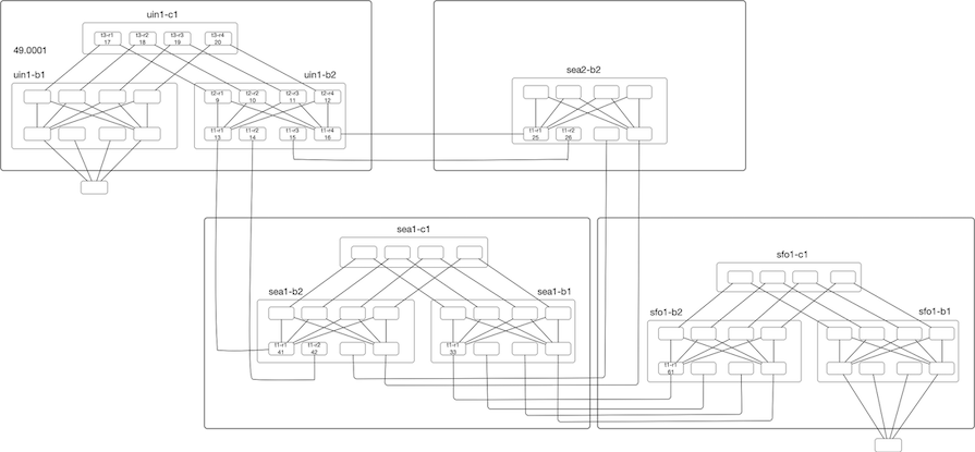
Now assume we are using a router with a radix of 32x100G and want to deploy a three-level Fat-Tree(32,3). We will have a total of 1280 with 512 leaf nodes for a single fabric, providing a bisection bandwidth of 819T. If we deploy ten instances of this fabric, we are looking at a topology size greater than >12k Nodes. This is a lot for any IGP to handle, and it worsens as the size grows. This inflation of Nodes (and links) comes from deploying this sort of dense topology to provide more bandwidth and directly impacts IGP scaling in terms of Flooding, LSDB size, SPF runtimes, and frequency of SPF run.
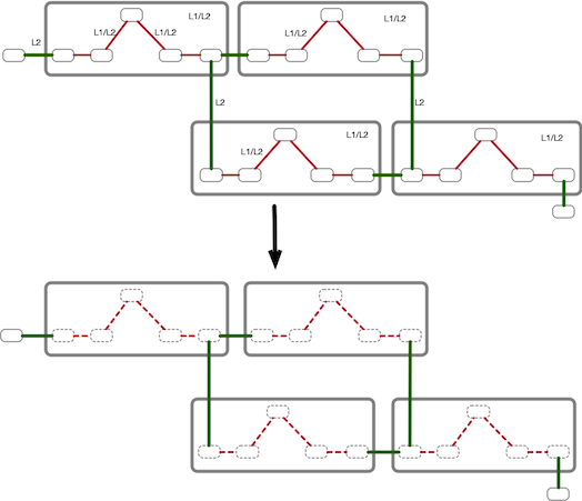
So one thought would be to make the internal fabric links as L1 only and the links between the fabrics as L2 like below, with red links as L1 only and green links as L2 only.

However, as you know that L1 is stub only; they can not be Transit. So that’s not going to work for us. If we want to use them as Transit, we will have to make L1 only links as L1/L2 like below:

But with this arrangement, we have not achieved anything compared to running a flat level2 and perhaps made it worse by running both L1 and L2 vs. running L2 only domain.
Another thought could be why not just use some sort of tunnel from the edge L2 routers in fabric to other edge routers in the same fabric and make those tunnel interfaces as L2. In this way, there is a contiguous L2 domain. We will table this line of thinking for now and ask, What if we can abstract these transit fabrics as a single node, in a way that each fabric presents itself as one big fat node to the external world.
Applying the same abstraction to our topology, we are looking at the topology of six nodes vs. seventy node topology. Similarly, In our earlier example of Fat-Trees (32,3), every Fat-Tree instance of 1280 Nodes is abstracted as a single node to the rest of the network and reducing the topology from 12800 Nodes to ~10 Nodes from an edge nodes perspective.
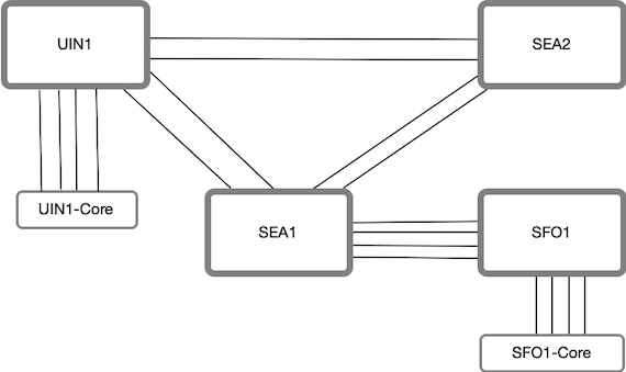
This sort of abstraction is what Area-Proxy provides us.
Area Proxy Details
We need to make the following changes to our flat level-2 topology to implement Area Proxy.
  1. Make the routers in a fabric from L2 to L1/L2 and internal fabric links as L1-L2 type.
  2. Tag the links between the fabrics as Area Proxy Border links. This allows the abstraction not to leak to the outside world.
  3. Configure Area Proxy System Identifier, which identifies the fabric as a single Node.
In our topology, we have configured Area Proxy on all the fabrics.
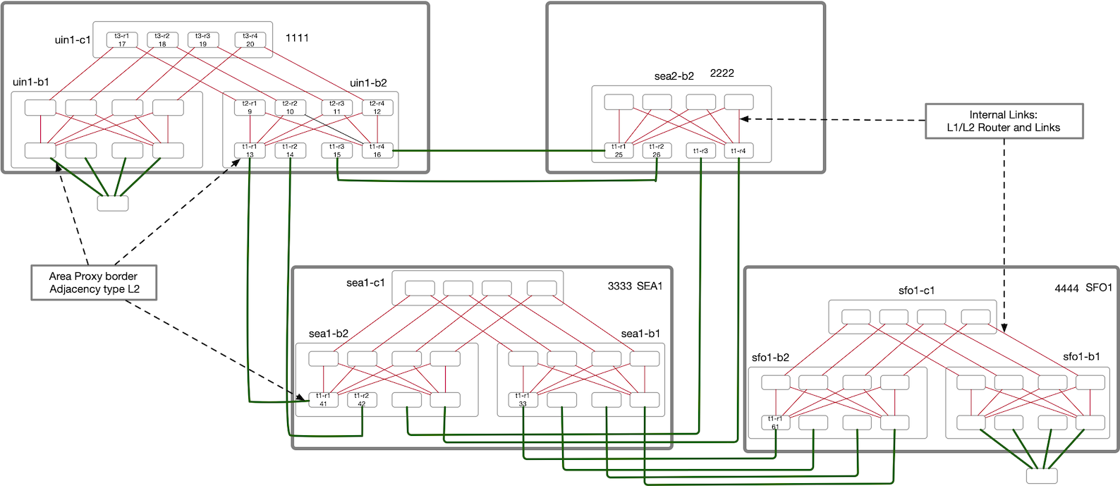
This scheme results in two types of routers for a given fabric:
- Inside Routers: These are the routers inside the fabric, like T2 and T3 routers in our fabric. They are running both Level1 and Level2 ISIS and have the details of the internal topology.
- Edge Routers: These routers are the edge nodes for a given Area proxy. In our topology, it will be the T1 nodes and their links to the other fabrics will be tagged as Area proxy boundary.
The result is now the edge nodes only see the fabrics as abstracted nodes, and our 70 Nodes topology gets reduced to 6 Node, from an external perspective.
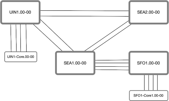
uin1-core1#show isis database (70 Nodes to only 6 Nodes)

IS-IS Instance: Gandalf VRF: default
  IS-IS Level 2 Link State Database
    LSPID                   Seq Num  Cksum  Life Length IS Flags
    uin1_core1.00-00             45  29531  1033    174 L2 <>
    sfo1_core1.00-00              45  20344  1178    174 L2 <>
    uin1.00-00                         14  46253   588    763 L2 <>
    SEA2.00-00                         11   6229   824    355 L2 <>
    SEA1.00-00                         19  59624   847    763 L2 <>
    SFO1.00-00                         20  28620   564    763 L2 <>
Within each area proxy domain, there is an area leader whose job is to generate an L2 LSP representing the abstracted topology. From an outside perspective, All the internal addresses looks like they are attached to this abstracted Node. By default, area leader is the router with the highest IP address in the abstracted topology highlighted in blue in our topology.
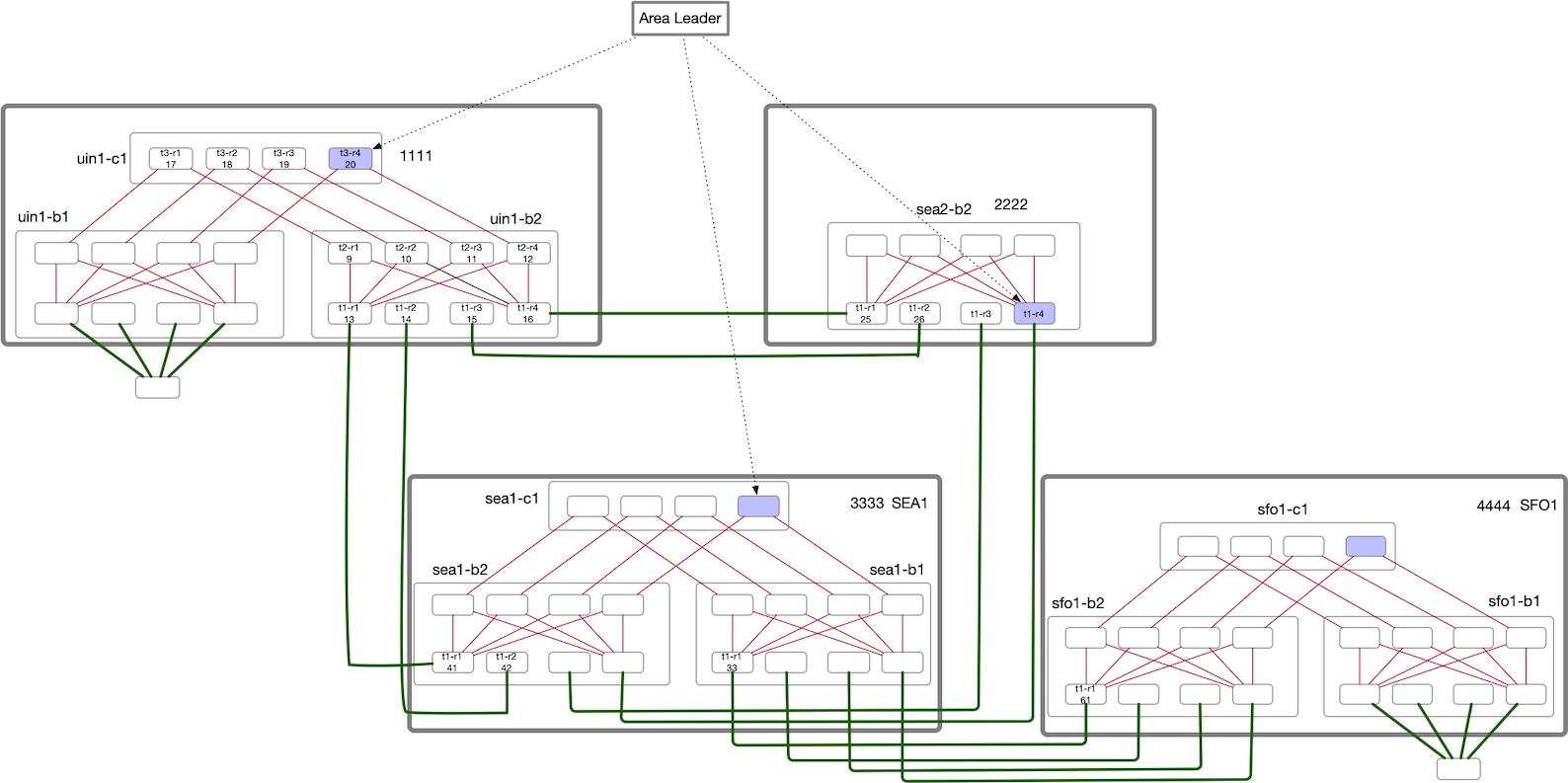
Below output of the SFO1.00-00 L2 LSP shows the Area leader Loopback listed as the Interface address. You can also see
the IS Neighbor for SFO1.00 is listed as SEA1.00.
uin1-core1#show isis database SFO1.00-00 detail

IS-IS Instance: Gandalf VRF: default
  IS-IS Level 2 Link State Database
    LSPID                   Seq Num  Cksum  Life Length IS Flags
    SFO1.00-00                  137  38958  1015    763 L2 <>
      Remaining lifetime received: 1199 s Modified to: 1200 s
      NLPID: 0xCC(IPv4)
      Hostname: SFO1
      Area address: 49.0001
      Interface address: 10.0.0.68                    <-- Area Proxy Leader Loopback IP
      IS Neighbor          : SEA1.00             Metric: 10  <-- Neighbor
      IS Neighbor          : SEA1.00             Metric: 10  <-- Neighbor
      IS Neighbor          : SEA1.00             Metric: 10  <-- Neighbor
      IS Neighbor          : SEA1.00             Metric: 10  <-- Neighbor
      IS Neighbor          : sfo1_core1.00       Metric: 10  <-- Neighbor
      IS Neighbor          : sfo1_core1.00       Metric: 10  <-- Neighbor
      IS Neighbor          : sfo1_core1.00       Metric: 10  <-- Neighbor
      IS Neighbor          : sfo1_core1.00       Metric: 10  <-- Neighbor
      Reachability         : 10.1.2.20/30 Metric: 10 Type: 1 Up
      Reachability         : 10.1.2.16/30 Metric: 10 Type: 1 Up
      Reachability         : 10.1.2.12/30 Metric: 10 Type: 1 Up
      Reachability         : 10.1.2.8/30 Metric: 10 Type: 1 Up
      Reachability         : 10.1.1.88/30 Metric: 10 Type: 1 Up
      Reachability         : 10.1.1.92/30 Metric: 10 Type: 1 Up
      Reachability         : 10.0.0.57/32 Metric: 10 Type: 1 Up
One benefit immediately jumps out is that a change in an internal topology (like an adjacency flap) that would have triggered a full SPF is now only a Partial SPF run. This is because all the Internal IP addresses are not attached to the Abstracted Node.
All the routers inside a given Area Proxy domain advertise an L1 LSP and L2 LSP. As part of L2 LSP advertisements, they add an Area Proxy TLV (Type 20), which indicates to the Area leader that the node is participating in the Area Proxy. Area Leader then generates a Proxy L2 LSP from these L2 LSP advertisements but doesn’t add Area proxy TLV, which is leaked to the rest of the network by the Edge routers.
The job of the edge routers is to only leak Area Proxy L2 LSP generated by the Area leader and prevent other inside L1/L2 LSPs to flood outside the area proxy. If an edge router sees a Level2 LSP, that contains the Area proxy TLV, it filters it. Edge Routers also uses the Area Proxy System ID to acknowledge the LSPs as part of sending PSNPs.
Metrics
The cost of transiting the abstracted Area proxy Node is considered zero. In our topology, we have the default cost of 10 for IS-IS. So in order to reach from UIN1 to SFO1 core, the IS-IS metric cost is 50.
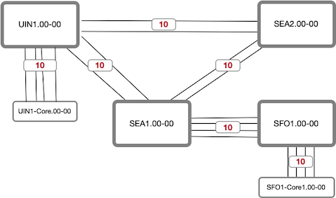
uin1-core1#show ip route 10.0.0.70

 I L2     10.0.0.70/32 [115/50] via 10.1.0.81, Ethernet1
                                via 10.1.0.85, Ethernet2
                                via 10.1.0.89, Ethernet3
                                via 10.1.0.93, Ethernet4
Similarly, If the edge wants to reach out to an internal fabric Node, the cost will be the sum of the L2 links between area-proxy domains and does not add the cost of transiting a fabric.
uin1-core1#show ip route 10.0.0.37 (sea1-b2-t2-r1)

 I L2     10.0.0.37/32 [115/30] via 10.1.0.81, Ethernet1
                                via 10.1.0.85, Ethernet2
                                via 10.1.0.89, Ethernet3
                                via 10.1.0.93, Ethernet4
Inside Router ignores their own Area Proxy LSP for SPF computation. In order to avoid loops and have consistency, the general rule is:
- Path with the lower inter-area proxy metric is preferred, regardless of any Intra-Area proxy cost.
- If the two paths have equal total Inter-area proxy metrics, then Intra area proxy metrics would be used.
Let’s look at an example of uin1-b1-t2-r1 view to reach sea2-b2-t2-r1 (10.0.0.37).
uin1-b2-t2-r1#show ip route 10.0.0.37 detail

 I L2     10.0.0.37/32 [115/20] via 10.1.0.97, Ethernet1 uin1_b2_t2_r1 -> uin1_b2_t1_r1
                                via 10.1.0.101, Ethernet2 uin1_b2_t2_r1 -> uin1_b2_t1_r2
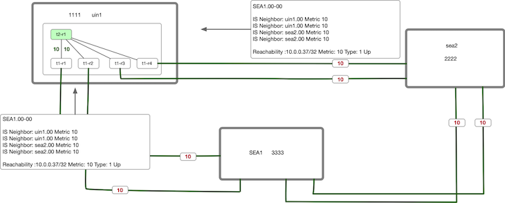
What we see is that the metric to reach sea2-b2-t2-r1 is 20. The reachability of sea2-b2-t2-r1 is advertised as part of
SEA1.00-00 L2 LSP. The Cost 20 is sum of uin1<-->SEA1 + The loopback cost. The cost via PDX2 is 30 which is more
hence the directly connected path with metric of 20 is preferred.
Given that uin1-b1-t2-r1 is an internal router, It chooses the lowest Inter-Area Proxy cost which is 20.Then we look at the
Intra-area metric and since the cost is same via uin1-b2-t1-r1 and uin1-b2-t1-r2, it ECMP between them as shown in the
above output.
If I increase the cost on one of the link from 10 to 50, then only one of the remaining interface will be used to reach the route
as shown below.
uin1-b2-t2-r1(config-if-Et2)#int eth1
uin1-b2-t2-r1(config-if-Et1)#isis metric 50
uin1-b2-t2-r1(config-if-Et1)#show ip route 10.0.0.37 detail

 I L2     10.0.0.37/32 [115/20] via 10.1.0.101, Ethernet2 uin1_b2_t2_r1 -> uin1_b2_t1_r2
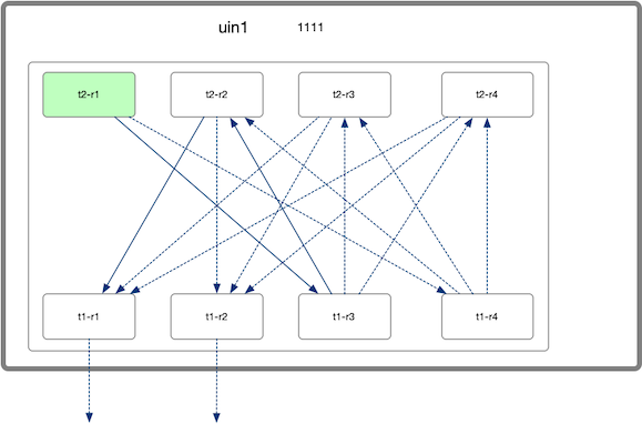
Now If I raise the cost on Ethernet2 as well, you can see now the routes are pointing towards router uin1_b2_t1_r[34]
with Metric of 20 which is our Inter-Area metric. From uin1_b2_t1_r[34] perspective, it’s pointing towards
uin1_b2_t2_r[234] to exit via uin1_b2_t1_r[12]. Basically now the Intra-area metric to exit t1-r[12] is shorter via
t1-r[34] –> t2-r[234] –> t1-r[12]. This shows how Inter and Intra area metrics are handled differently.
uin1-b2-t2-r1(config-if-Et2)#isis metric 50
uin1-b2-t2-r1(config-if-Et2)#show ip route 10.0.0.37 detail

 I L2     10.0.0.37/32 [115/20] via 10.1.0.105, Ethernet3 uin1_b2_t2_r1 -> uin1_b2_t1_r3
                               via 10.1.0.109,  Ethernet4 uin1_b2_t2_r1 -> uin1_b2_t1_r4

uin1-b2-t1-r3#show ip route 10.0.0.37 detail

 I L2     10.0.0.37/32 [115/20] via 10.1.0.126, Ethernet2 uin1_b2_t1_r3 -> uin1_b2_t2_r2
                                via 10.1.0.146, Ethernet3 uin1_b2_t1_r3 -> uin1_b2_t2_r3
                                via 10.1.0.166, Ethernet4 uin1_b2_t1_r3 -> uin1_b2_t2_r4


uin1-b2-t2-r2#show ip route 10.0.0.37 detail

 I L2     10.0.0.37/32 [115/20] via 10.1.0.117, Ethernet1 uin1_b2_t2_r2 -> uin1_b2_t1_r1
                                via 10.1.0.121, Ethernet2 uin1_b2_t2_r2 -> uin1_b2_t1_r2
Flooding
An internal change in a given Area-Proxy domain will cause the Internal routers to flood within the fabric via L1 and L2 LSPs which will make Area Leader learn about that change. The Area leader then will generate an updated L2 LSP with updated reachability info which will get flooded to the rest of the network.
When the neighboring area-proxy domain receives this LSP, it get’s flooded like in a similar way like we saw in the previous blog post and there are no optimization with area-proxy itself on how flooding is handled.
Also, because we have both L1 and L2 running in an area-proxy domain, there will be a natural increase in the amount of flooding within an area-proxy domain; however, I think this is not an issue, especially with mature IS-IS stacks.
Closing Thoughts
We started with a problem on how the dense topologies, the size of the LSDB can explode and how using Area-Proxy, we can abstract these topologies. This abstraction is quite powerful and should help in IGP scaling in few ways:
- Reduction of LSDB size. We should expect SPF improvements from the perspective of Edge Nodes(LER), which are generally more CPU taxed than Core Nodes, as from their perspective, the complexity of the graph is simplified. However, this may not be a problem for most networks.
- All the internal topology changes will look like PRC rather than a full SPF (Link Up/Link Down).
- Topologies change still needs to be flooded, and there will be redundant flooding, and there is no improvement to reduce the redundant flooding. However, given that the number of LSPs is reducing at the network level, there could be some global flooding improvements (at the expense of an increase in the number of L1/L2 LSP in an area-proxy domain). I could be wrong here, so please don’t quote me on this, as I haven’t measured it.
I am not aware of any work happening yet to integrate this with RSVP-TE extensions. It would be good to see some work in this area. My thoughts on this are:
- Flooding the Extended IS Reachability TLV extensions for TE for the links between Area-Proxy domain seems Trivial.
- The challenge is that because the whole fabric is abstracted as a node, a Headend doing CSPF doesn’t know the internal state of the fabric and will see them as a single Node.
- One can assume that the long-haul links will always be expensive and be the bottleneck before the fabric runs out of capacity.
- Edge Nodes will have complete understanding of the internal topology bandwidth reservation state and will need a way to track/tie the RSVP reservations signaled by the Headend to the internal topology bandwidth reservation state.
With this, I conclude this post. I hope you found this helpful.