IS-IS Average Flooding Rate
Introduction
In recent years, a lot of work has been done to scale IGPs for dense topologies, making IGPs again an interesting area. In this blog post, we will look at IS-IS Flooding and how we can measure the flooding rate, and in the future post explore Dynamic Flooding and Area Proxy.
Topology Setup
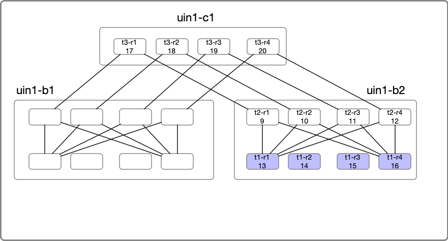
For our experiment, we will use a stripped-down topology connecting Four locations. The devices are emulated using Arista cEOS, and all devices are part of a single level2 flooding domain. Topology creation was done with the help of netsim-tools and containerlabs. So my regards go to everyone involved with the tool, as it took care of the monotonous work like IP-Addressing, wiring, and base configs.
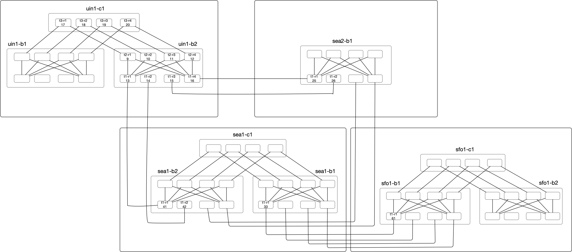
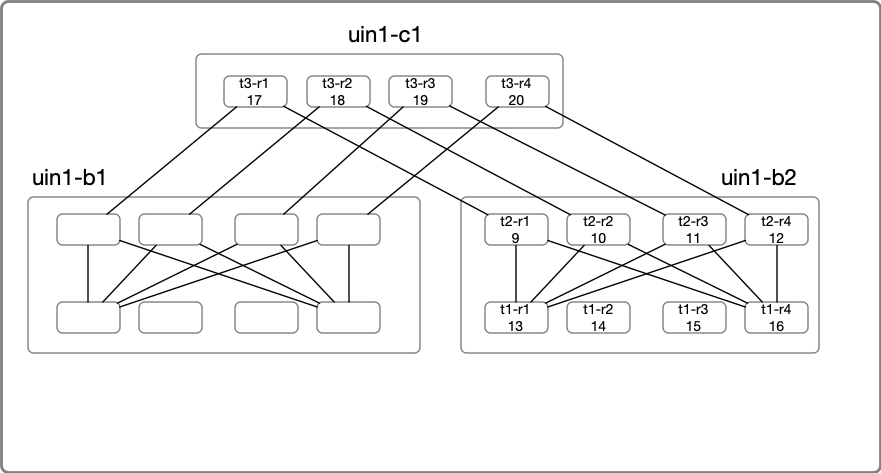
In the above diagram, Nodes under uin1-b2 will be the primary focus of our deep dive. Node Label consists of the node name
suffix and the last octet of the loopback IP. For example:
uin1-b2-t1-r1 with LSP ID of 0000.0000.0013 is highlighted as t1-r1(13) under uin1-b2 block.
uin1-b2-t2-r1 with LSP ID of 0000.0000.0009 is highlighted as t2-r1(09) under uin1-b2 block.
IS-IS Refresher
Let’s do a quick IS-IS refresher. We know that IS-IS Packets are of following types:
- IS-IS Hello (IIHs)
- LAN Level1 IIH
- LAN Level2 IIH
- P2P IIH
- Link state Protocol Data Unit (LSPs)
- Sequence Number Protocol Data Unit (SNPs)
- Partial Sequence Number Protocol Data Unit (PSNP)
- Complete Sequence Number Protocol Data Unit (CSNP)
IS-IS hello packets are for IS-IS adjacency management, and we will skip them here.Our focus will be on P2P adjacencies and respective behavior of SNPs PDUs.
Link State PDU (LSPs)
LSPs are the smallest unit of LSDB which encodes the topology information. Each LSP is identified by its LSP ID, and Sequence number identifies the most recent version of the LSP.Sequence numbers are Unsigned 32-bit integer starting at 0x00000001 through 0xFFFFFFFF (136 years to reach maximum if originated every second).
The format of LSP-ID is <System-ID> + <PseudoNode-ID>+ <Fragment-ID> and displayed as xxxx.xxxx.xxxx.yy-zz.
x stands for the System-ID digits, y stands for the pseudonode-ID, and z represents the fragment number.
I have seen some confusion around the Fragment-ID. Unlike OSPF, IS-IS runs directly on top of the layer two rather than IP, so it doesn’t have a built-in fragmentation function for larger MTU-sized packets. which means IS-IS needs to build the fragmentation support itself.
So, If an IS-IS router with LSP-ID 0000.0000.0013 has to originate a 4000 byte LSP and its IS-IS MTU is 1492 bytes. It
will need to transmit three fragments. The LSP-IDs of each fragment will be 0000.0000.0013-00, 0000.0000.0013-01,
and 0000.0000.0013-02. These LSP fragments are treated independently, except there are specific rules around fragment
zero that an IS-IS speaker has to obey. For example, IS-IS does not care if any non-zero fragment is lost but if a
Fragment Zero is not present, then the entire set of fragments will be declared invalid. There are some other considerations
one needs to be aware of, like how an IS-IS implementation packs the updates across multiple fragments and whether a topology
change will cause an unnecessary churn due to updates getting packed differently across fragments.
Below is an output of how the LSDB looks like:
uin1-b2-t1-r1#show isis database

IS-IS Instance: Gandalf VRF: default
  IS-IS Level 2 Link State Database
    LSPID                   Seq Num  Cksum  Life Length IS Flags
    uin1_b1_t2_r1.00-00           4  13589  1105    201 L2 <>
    uin1_b1_t2_r2.00-00           3   6754  1105    201 L2 <>
    uin1_b1_t2_r3.00-00           3  49643  1105    201 L2 <>
    uin1_b1_t2_r4.00-00           3  52236  1105    201 L2 <>
    uin1_b1_t1_r1.00-00           4   6817  1106    201 L2 <>
    uin1_b1_t1_r2.00-00           5  56751  1106    201 L2 <>
    uin1_b1_t1_r3.00-00           4   8512  1108    201 L2 <>
    uin1_b1_t1_r4.00-00           4  42127  1107    201 L2 <>
    uin1_b2_t2_r1.00-00           6  24013  1105    201 L2 <>
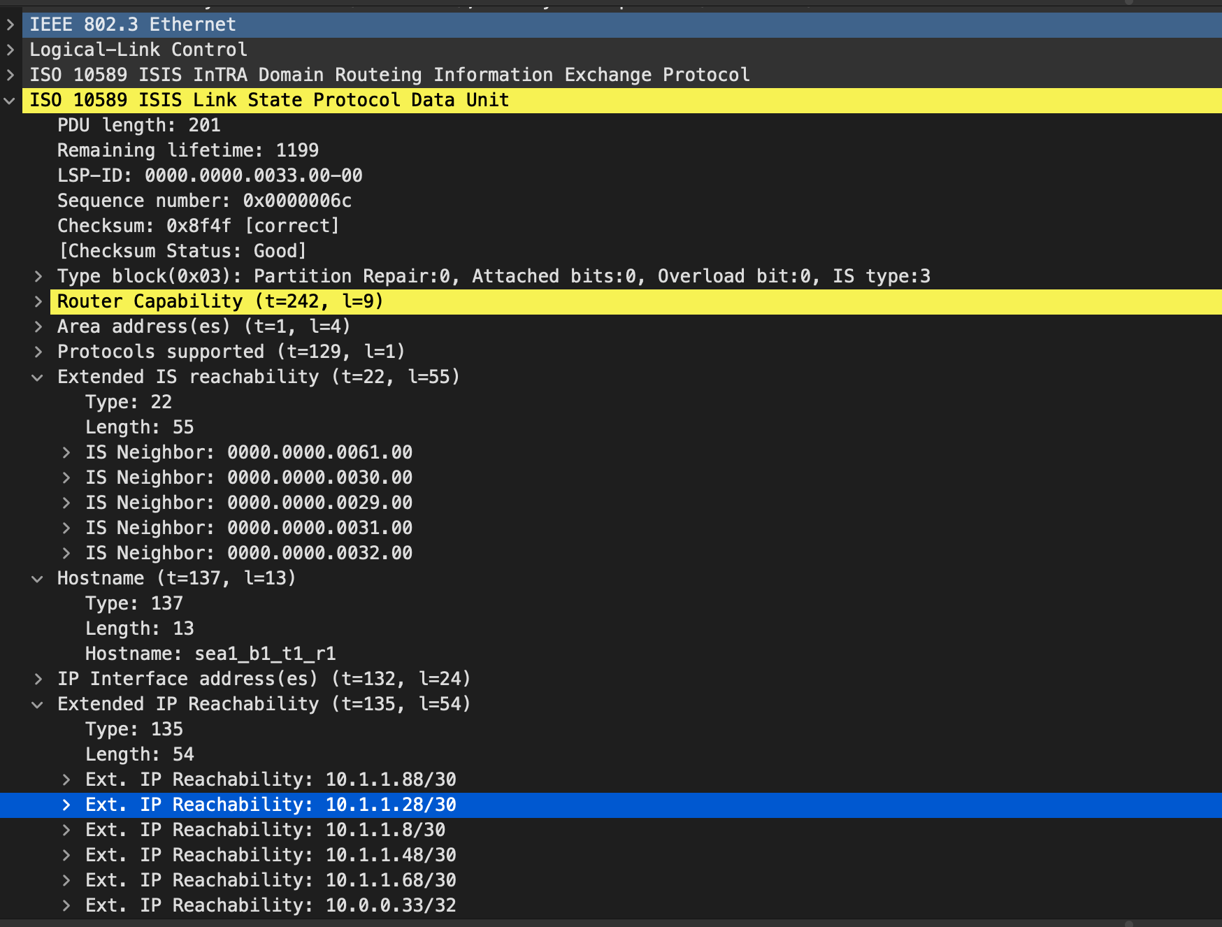
For example, below is an LSP with LSP-ID: sea1_b1_t1_r1.00-00 and a Sequence number of 5.If we look at the details of the LSP, we can see how router “sea1_b1_t1_r1” is connected with other neighbors, metric, reachability info etc. An LSP is a general envelope to tell all sorts of info, for example, If we would have enabled RSVP-TE in the network, then it would have contained necessary bandwidth related details which is required to build the TED.
uin1-b2-t1-r1#show isis database detail sea1_b1_t1_r1.00-00

IS-IS Instance: Gandalf VRF: default
  IS-IS Level 2 Link State Database
    LSPID                   Seq Num  Cksum  Life Length IS Flags
    sea1_b1_t1_r1.00-00           5  32200   631    201 L2 <>
      Remaining lifetime received: 1199 s Modified to: 1200 s
      NLPID: 0xCC(IPv4)
      Hostname: sea1_b1_t1_r1
      Area address: 49.0001
      Interface address: 10.1.1.69
      Interface address: 10.1.1.89
      Interface address: 10.1.1.49
      Interface address: 10.1.1.9
      Interface address: 10.1.1.29
      Interface address: 10.0.0.33
      IS Neighbor          : sfo1_b2_t1_r1.00    Metric: 10
      IS Neighbor          : sea1_b1_t2_r1.00    Metric: 10
      IS Neighbor          : sea1_b1_t2_r3.00    Metric: 10
      IS Neighbor          : sea1_b1_t2_r2.00    Metric: 10
      IS Neighbor          : sea1_b1_t2_r4.00    Metric: 10
      Reachability         : 10.1.1.68/30 Metric: 10 Type: 1 Up
      Reachability         : 10.1.1.88/30 Metric: 10 Type: 1 Up
      Reachability         : 10.1.1.48/30 Metric: 10 Type: 1 Up
      Reachability         : 10.1.1.8/30 Metric: 10 Type: 1 Up
      Reachability         : 10.1.1.28/30 Metric: 10 Type: 1 Up
      Reachability         : 10.0.0.33/32 Metric: 10 Type: 1 Up
      Router Capabilities: Router Id: 10.0.0.33 Flags: []
        Area leader priority: 250 algorithm: 0
here is the mandatory pcap
PSNP and CSNP
We saw that LSP PDUs are the building blocks of LSDB. Now the goal of the PSNP and CSNP is to keep the LSDB in sync. The goal of the CSNP is to publish all the headers of the link-state database to the neighbor. After receiving a CSNP, the neighboring router may decide to request an Updated LSP if it has an older LSP version. Asking for a recent version of LSP is done by sending PSNP.
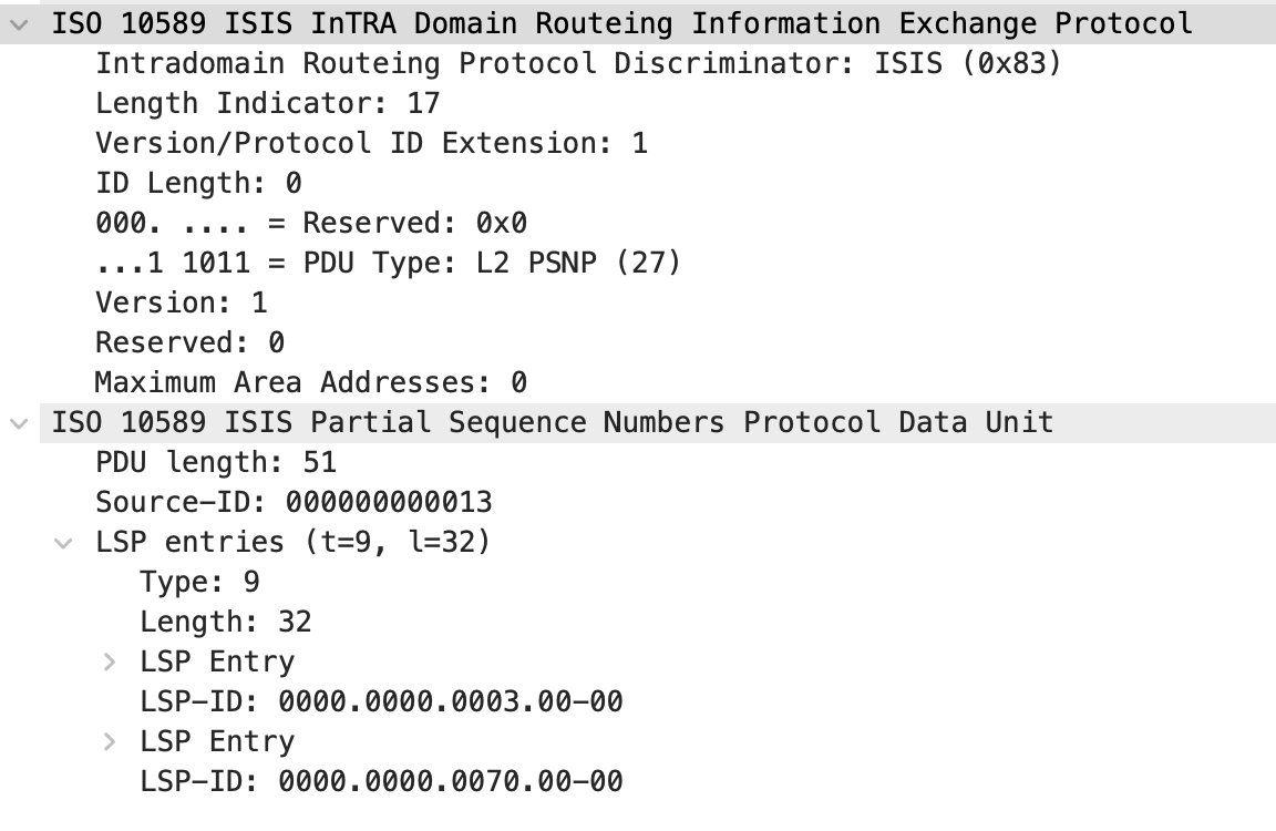
Another use of PSNP is to acknowledge that the neighbor has received an LSP. Think like a TCP Ack. On P2P links, when an LSP Update is sent, an internal SRM(Send Routing Message) flag is set, which means now the router is waiting for an acknowledgment which the neighbor will do by sending PSNP message. If the router receives the acknowledgment, SRM flag is cleared and removed from the retransmission list. If the router doesn’t receive an acknowledgment, the router will retransmit the LSP. That’s the IS-IS mechanism for providing reliable delivery.
When a router is trying to acknowledge an LSP by sending PSNP, it will have an internal SSN (Send Sequence Numbers) flag set indicating that LSP should be included in the next PSNP PDU. From an implementation perspective, most implementations will try to be efficient by waiting for a certain time to acknowledge multiple LSPs by sending a single LSP.
Below is an example of a PSNP acknowledging for two LSPs.
IS-IS Flooding
Some example of events that cause flooding of new information in IS-IS are:
- Adjacency State.
- Metric Cost change.
- RSVP Bandwidth change above certain threshold.
When a Router originates an LSP, it will send out on all the interfaces with an adjacency in the Up State. A receiving router will verify if the received LSP is newer (with a higher sequence number) than the one installed in the local database. If the sequence number is less than or equal to the LSP in the database, the router discards the LSP and sends a PSNP to acknowledge the received LSP. If the LSP has a higher sequence number, it will update the LSDB and further send it on all the interfaces except the one from which it received the LSP.
Every LSP also has a lifetime, so they require periodic refresh regardless of any topology change to help protect against stale entries in the LSDB.
In our topology, If I go and disable the link between sea1_b1_t1_r1 <--> sfo1_b2_t1_r1, then that will be a topology
change from both routers sea1_b1_t1_r1, and sfo1_b2_t1_r1 perspective. Both will send an Updated LSP with a higher
sequence number telling the rest of the network about the change. Each router receiving the Updated LSP will update the
local LSDB and flood the LSP further.
Microscopic view of an IS-IS Flood event
Now that we have covered a bit of background, we will trigger an LSP flooding event by disabling the link between
sea1_b1_t1_r1 <--> sfo1_b2_t1_r1 and then enable it again. A single link disable event will trigger to LSP updates,
one from sea1_b1_t1_r1, and other from sfo1_b2_t1_r1. Once we enable the link again, both routers will send another
LSP update about the link comping up.
We will capture the events by taking a tcpdump capture on all the interfaces, merging the captures, and then using t-shark to convert them into CSV for analysis. The captures are taken on the T1 routers highlighted in blue.
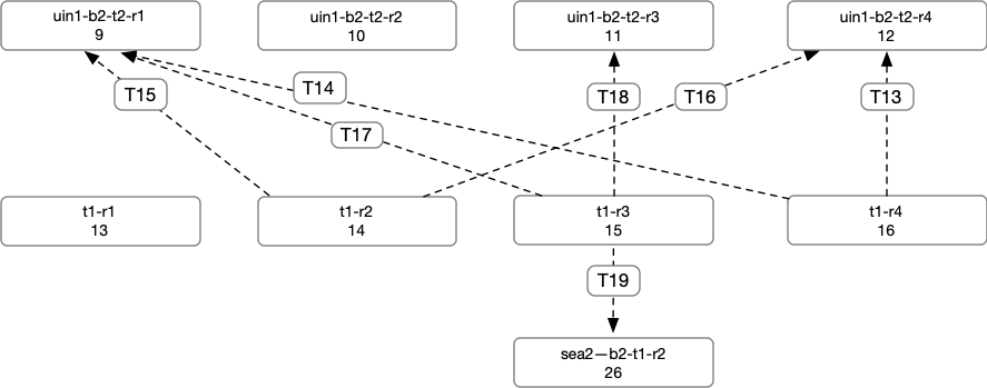
Below is the sequence of events we see for the LSP generated by sea1_b1_t1_r1:
- T0:
sea1-b2-t1-r1->uin1-b2-t1-r1 - T1 - T4:
uin1-b2-t1-r1->uin1-b2-t2-r[1234]. At this point all the Routers at T2 layers have an updated LSP Update.

- T5 - T7:
uin1-b2-t2-r3->uin1-b2-t1-r[234]. We seeuin1-b2-t2-r3sends an update touin1-b2-t1-r[234]. We can see thatuin1-b2-t2-r3didn’t send it back touin1-b2-t1-r1.

- T8, T10 - T11:
uin1-b2-t2-r2->uin1-b2-t1-r[234]. We see nowuin1-b2-t2-r2sending similar updates touin1-b2-t1-r[234] - T9:
sea1-b2-t1-r2->uin1-b2-t1-r2. Becauseuin1-b2-t1-r2received the update fromsea1-b2-t1-r2before it getsuin1-b2-t2-r2.uin1-b2-t1-r2will flood this update to T2 Routers. - T12:
uin1-b2-t1-r4->sea2-b1-t1-r1

- T13, T14:
uin1-b2-t1-r4->uin1-b2-t2-r[14]. - T15, T16:
uin1-b2-t1-r2->uin1-b2-t2-r[14]. - T17, T18:
uin1-b2-t1-r3->uin1-b2-t2-r[13]. - T19:
uin1-b2-t1-r3->sea2-b1-t1-r2.
You can explore the timelines by yourself here. The cluster shows how the updates came in. The first cluster of events
are for LSP events from sea1_b1_t1_r1 followed by sfo1_b2_t1_r1 and the last cluster on the very right is the LSP
Ack events (PSNPs) for both LSP events.
Computing Average Flooding Rate
If you are running IS-IS with dense topologies and worry about Flooding, then the first thing you would want is to measure how much Flooding is happening in the network. This is pretty straightforward to do so. What we have to do is:
- Take LSP snapshots at regular intervals. Let’s say every five mins.
- Take the difference between the LSP Sequence Numbers to know how many LSP updates each LSP has between snapshots.
- Sum all the changes and divide them by the snapshot interval. In our case, 5 mins.
The above method will explain how much Flooding is happening in the network. In our topology, if I have to measure the average flooding interval, it will be almost a no event which there is no churn like a real network will have. So I am going to use a bash script on one of the box to periodically enable/disable interface at regular intervals.
Below is the sample code to collect the output of show isis database level-2 which can be captured from any node in the
topology.
import json
import ssl
import time
import pandas as pd
from jsonrpclib import Server
from datetime import datetime

_create_unverified_https_context = ssl._create_unverified_context
ssl._create_default_https_context = _create_unverified_https_context

switch = "172.20.20.54"
username = "admin"
password = "admin"

urlString = "https://{}:{}@{}/command-api".format(username, password, switch)
switchReq = Server( urlString )

df_list = []
max_observations = 72
observation = 0
while observation <= max_observations:
    print(f"Collecting {observation} ")
    now = datetime.now()
    current_time = now.strftime("%d/%m/%Y %H:%M:%S")
    response = switchReq.runCmds( 1, ["show isis database level-2"] )
    lsps_dict =  response[0]['vrfs']['default']['isisInstances']['Gandalf']['level']['2']['lsps']
    df = pd.DataFrame.from_dict(lsps_dict, orient='index').reset_index().rename(columns={'index':'lsp_id'})
    df['time'] = current_time
    df_list.append(df)
    observation += 1
    time.sleep(300)

final_df = pd.concat(df_list)
final_df.to_csv("final_lsp_seq.csv", index=False)
Next step is to read the lsp data, take the diff and plot it.
df = pd.read_csv("~/Downloads/final_lsp_seq.csv") ## Read the LSP Data.
df['time'] = pd.to_datetime(df['time'])           ## Fix the Time Column.
df = df[['time', 'lsp_id','sequence']]            ## Capture relevant columns
#b16 = lambda x: int(x,16)                        ## Needed when the LSP Seq Numbers are hex.
#df['sequence'] = df['sequence'].apply(b16)       ## Needed when the LSP Seq Numbers are hex.
df = df.set_index(['time', 'lsp_id'])             ## Set Time and LSP ID as Seq Number

## Take a groupby by LSP_ID and take a diff on the Seq Nummber. Unstack the columns and Fill NAN with zeros.
lsp_avg = df.groupby(level=1)['sequence'].diff().unstack(level=1).fillna(0)
## Divide it by 300 seconds to get a Average LSP Flooding per second.
lsp_avg = lsp_avg.sum(axis=1).iloc[1:]/300
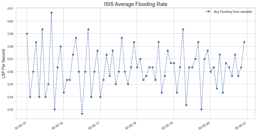
The graph has about ~.5 LSPs per second, which is not a lot, but this is a toy example. Data for real busy networks will
look very different.
Conclusion
In this post, we started with some basics of IS-IS and then looked at the microscopic view of a flooding event. Then we looked at a way to compute the Average flooding rate. A measuring method lets us know how bad a problem is and may curb the tendency to apply a solution blindly.